Control the robot with a simple script
Now it's time to give the robot some work to do. In the real world, a PLC would control the robot. We can connect this PLC to twin and the PLC would control the robot as if it were a real robot. In this tutorial we focus on the basics so we do not use a real PLC to control the robot. We use a simple script instead, which we can write within twin. This script should act as the controller for the robot.
Adding a script
Scripts are a very powerful tool to add some logic to the simulation. A script is a simulation component which can be added via the simulation component library. Scripts can be found in the category Automation.
We want to build a very simple state-machine with the following steps:
- Move the portal above the pick position
- Create a new box, enable the gripper and move to the pick position
- Move back above the pick position
- Move to the drop position
- Disable the gripper and start again with step 1
After you have added a new ScriptComponent simulation component we need to add some inputs and outputs. You can do this by clicking on the plus-symbol next to the property InputDefinitions or OutputDefinitions. Please add three InputDefintions and four OutputDefinitions.
Tip
You can give meaningful names to the inputs or outputs. To do that, expand the desired InputDefinition or OutputDefinition an give it a name.
To store the current state of the state-machine we have to add a static variable to the script. This can be done by clicking on the plus-symbol near the Variables property. You can now expand the variables and change the Name of the new created variable to state.
Next we have to edit the script. By clicking on the edit button near the ScriptText property the default text editor opens and you can copy the following C# code into the editor:
// Define some constant robot positions in m for the x-, y- and z-axis
var abovePickPosition = new double[] {-0.22, 0.04, 0};
var pickPosition = new double[] {-0.22, 0.04, -0.05};
var dropPosition = new double[] {0.1, -0.1, 0};

// Define the axis speed in m/s
var axisSpeed = 0.1;

// Read the current position of each axis in m
var currentXPosition = Inputs.Get<double>(0);
var currentYPosition = Inputs.Get<double>(1);
var currentZPosition = Inputs.Get<double>(2);

// The state-machine to control the robot. The variable state is a static
// variable which is declared in the properties of the ScriptComponent.
switch (state)
{
	case 0:
		if (MoveTo(abovePickPosition))
		{
			state = 10;
		}

		break;

	case 10:
		EnableGripper(true);

		if (MoveTo(pickPosition))
		{
			state = 20;
		}

		break;

	case 20:
		if (MoveTo(abovePickPosition))
		{
			state = 30;
		}

		break;

	case 30:
		if (MoveTo(dropPosition))
		{
			state = 40;
		}

		break;

	case 40:
		EnableGripper(false);
		state = 0;

		break;
}

// Helper function to move each axis to the target position.
// Returns true when the target position is reached and false if not.
bool MoveTo(double[] targetPosition)
{
	var deltaX = currentXPosition - targetPosition[0];
	var deltaY = currentYPosition - targetPosition[1];
	var deltaZ = currentZPosition - targetPosition[2];

	var speed = new double[3];

	speed[0] = deltaX > 0 ? -axisSpeed : axisSpeed;
	speed[1] = deltaY > 0 ? -axisSpeed : axisSpeed;
	speed[2] = deltaZ > 0 ? -axisSpeed : axisSpeed;

	SetAxisSpeed(speed);

	return IsPositionReached(targetPosition);
}

// Helper function to set the speed of each axis.
void SetAxisSpeed(double[] speed)
{
	Outputs[0] = speed[0];
	Outputs[1] = speed[1];
	Outputs[2] = speed[2];
}

// Helper function to check, whether the given position is reached or not.
bool IsPositionReached(double[] position)
{
	var deltaX = currentXPosition - position[0];
	var deltaY = currentYPosition - position[1];
	var deltaZ = currentZPosition - position[2];

	return System.Math.Abs(deltaX) < 0.01
		&& System.Math.Abs(deltaY) < 0.01
		&& System.Math.Abs(deltaZ) < 0.01;
}

// Helper function to enable or disable the vacuum gripper.
void EnableGripper(bool enable)
{
	Outputs[3] = enable;
}
Tip
You can even edit the script while the simulation is running. When you save the script in the editor, it is applied in the simulation. You can try this for example by changing the value of the variable axisSpeed to 0.2 while the robot is moving.
Tip
You can set your preferred editor for editing scripts. To do this, open the Settings and change the Default Text Editor on the Application settings page.
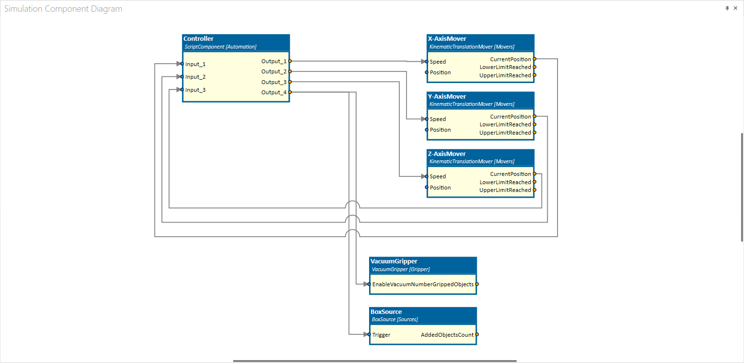
Linking all together
Now it's time to put all the stuff together, which means, we have to connect the axis-movers and the vacuum-gripper to the controller. This can easily be done in the Simulation Component Diagram.
Note
You can enable the Simulation Component Diagram window via the Windows drop-down button in the toolbar. When the window is activated, you will see the window by default as a tab below the 3D View window. If you want to reorganize the layout, just click and hold the Simulation Component Diagram tab and drop it on any place you like. You can dock the window into the layout or you can even move the window to a separate screen.
Please connect the signals as shown in the image below:
Let the robot do some work
We are ready to start the simulation! By clicking on the green play-button in the 3D View window, the simulation is started.
The portal robot should now start picking and stacking the boxes. If the stack becomes too high, you will see that the robot knocks the stack over.
Tip
Any of the configuration we made in the previous sections, can be done while the simulation is running. This is a very important feature. Imagine, you are building a very complex machine. You start testing your PLC code and at some point, you need to add a sensor or maybe you need to change some other configuration. Within twin you can do this at any time without restarting the whole simulation!
Summary
Congratulations, you build another digital twin of a machine with twin! As mentioned in the very beginning, this was a very basic tutorial with many simplifications which would make no sense in real life.
Nevertheless you learned the basics like:
- Importing a CAD model
- Working with the assembly structure
- Adding simulation components
- Linking the simulation components together
- Start the simulation
What next
Start building your own machines! Import the model and search through the simulation component library to add the functionality you need.