Build the 3D model
Start the simulation software twin. In the toolbar at the top of the main-window click the button New to create a new project. Projects are stored in directories. Create a new directory called GantryRobot and select that directory.
Import existing CAD data
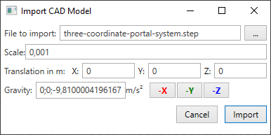
Please import the file three-coordinate-portal-system.step from the tutorials folder. You can import files by clicking on the Import button in the toolbar.
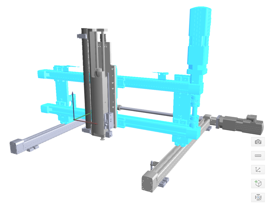
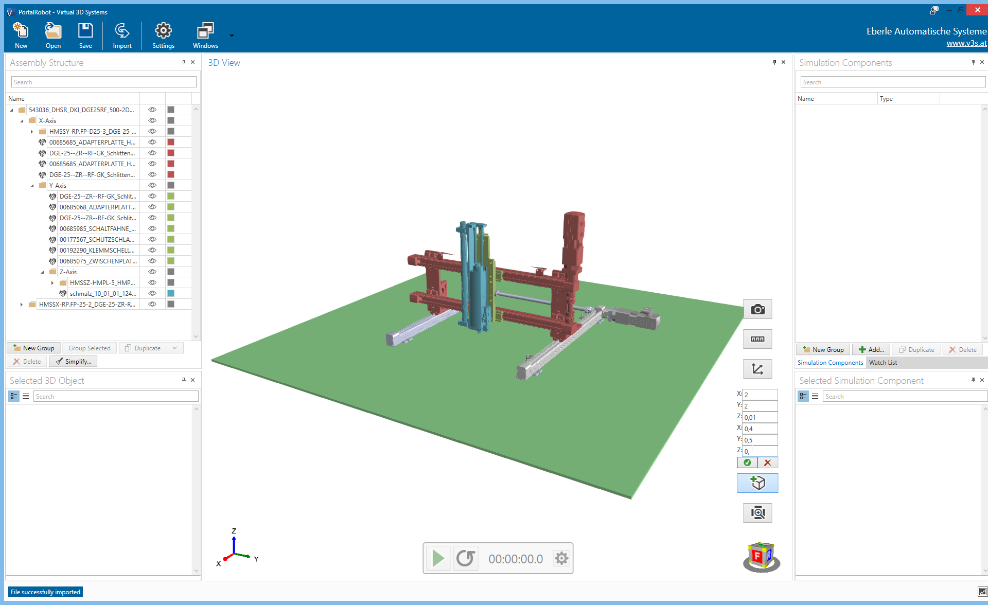
After you have clicked the button Import the file is imported. You will see a message in the status bar when the process is completed. After the model is imported the window will look like this:
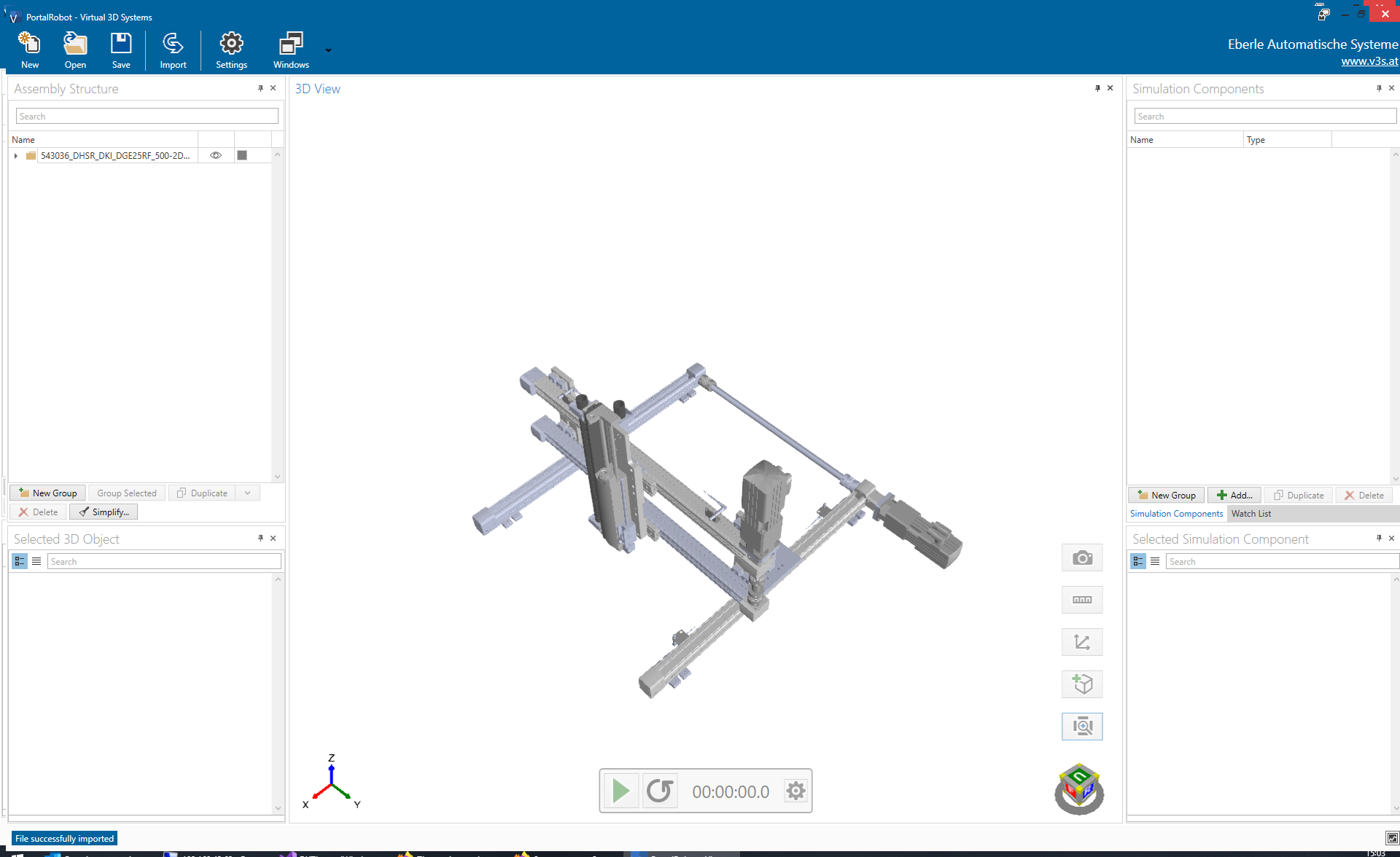
On the left side you can see the window Assembly Structure. Here you can navigate through the assembly structure. In the center you can see the window 3D View which shows the imported model.
Create a kinematic chain
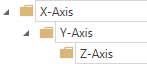
The portal robot consists of three axis, the x-, y- and z-axis. We want the axis to move in relation to each other. That means, all 3d-object from all axis should move, when the x-axis is moving. We can achieve this by arranging the 3d-objects in a kinematic chain which looks like this:
In most cases, the imported assembly structure is not arranged in this way. This is because most mechanical engineers build the assembly with production in mind.
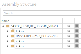
Within twin you can easily group 3d-objects and re-arrange these groups. We first select all 3d-objects, belonging to the x-axis. Therefore we expand the assembly tree in the Assembly Structure window and select the following group:
We can see, that all 3d-objects within this group are colored blue in the 3D View window. You may notice, that not all 3d-objects are selected. You can add these missing 3d-objects to the selection by holding the CTRL key and clicking on the objects in the 3D View window. The selection should now looks like this:
When all 3d-objects are selected, you can create a new group which contains all the selected objects by clicking on Group Selected in the Assembly Structure window. This creates a new group which is named New Group (1). You can give the group a more meaningful name like X-Axis.
Next, we put all 3d-objects which builds the y-axis into a new group. We select the seven 3d-objects according to the image below:
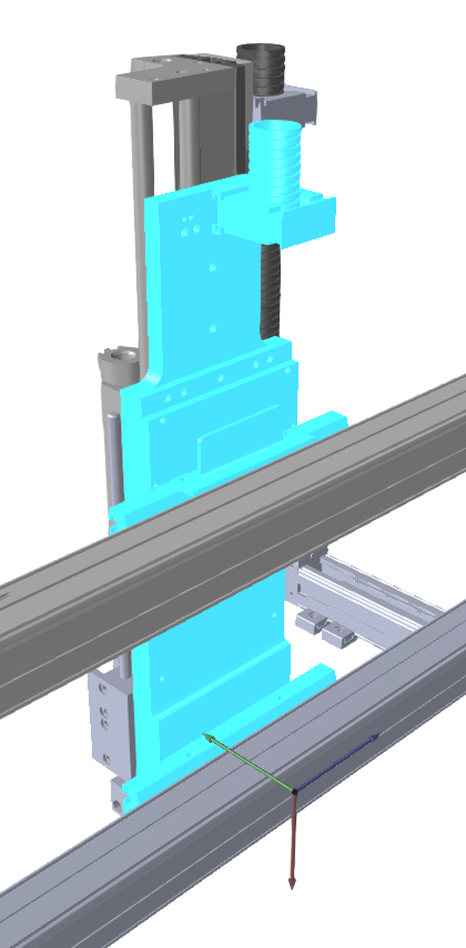
Again we put the selected 3d-objects into a new group by clicking Group Selected in the Assembly Structure window. We can rename the new created group to Y-Axis.
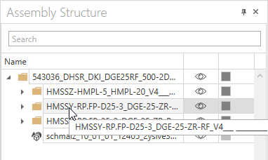
To build the z-axis, we can select the group HMSSZ-HMPL-5_HMPL-20_V4___ _________ in the Assembly Structure. The vacuum gripper is also part of the z-axis, so we have to add the 3d-object to the selection. The selected 3d-objects should now look like this:
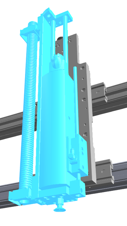
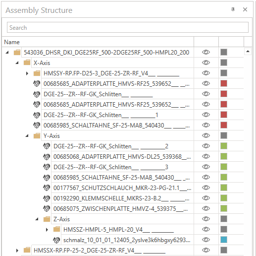
By clicking Group Selected in the Assembly Structure window, we put the selected 3d-objects into a new group, which we name Z-Axis. Now we have an assembly structure which looks like this:
Tip
To verify, if all necessary 3d-objects are contained in each group, you can select a group in the Assembly Structure window and check the selected 3d-objects in the 3D View window.
As mentioned at the beginning of this topic, we have to re-arrange these newly created groups. We can simply select a group in the Assembly Structure window and move it into another group by drag & drop. The final structure looks like this:
Change the color of a 3d-object
To get a better orientation within our machine, we can colorize 3d-objects. It is possible to change the color of a single 3d-object or the color of a whole group. In this tutorial we will change the color of the three axis according to the following table:
| Group | Color |
|---|---|
| X-Axis | Red |
| Y-Axis | Green |
| Z-Axis | Blue |
Create a floor
To create a floor, we can add a new cube. This can be done by simply clicking on  in the
 3D View window. This opens an area where the properties of the cube can be defined, as you can see in the image below.
Please use the values from the table below to create the floor object:
| Property | Value in m |
|---|---|
| X | 2 |
| Y | 2 |
| Z | 0.01 |
| X | 0.4 |
| Y | 0.5 |
| Z | 0 |
By clicking on  the cube is added to the assembly structure. You can now rename the cube to
 Floor.
Tip
The green color of the cube indicates, that you are still in editing mode. You can now change the size and position of the cube. After clicking on the cube gets gray which indicates, that the cube was added to the assembly structure.
Next
In the next chapter we will start bringing some physics to the portal robot.