Add actors to the robot
In this chapter you will learn how to add actors to the model. With actors you can for example move the axes or create workpiece objects.
What are simulation components
Within twin, all actors, sensors, mathematical blocks, connections to external devices and so on are called simulation components. With simulation components you can bring your imported model to live. Simulation components can be added either by clicking on  in the
 Simulation Components window or via the context menu in the Simulation Component Diagram window.
Tip
If the Simulation Component Diagram window is not visible, you can enable it in the Windows drop-down button in the tool bar.
Move the axis
In the previous chapter we re-organized the imported 3d-objects in a way, that they can move in relation to each other. In order to move them, we have to add some actors. In the real world, all axis are controlled by an external controller. The controller knows the position of each axis. That means, we have to move the axis according to some given positions.
We can do this by using the simulation component KinematicTranslationMover which is located in the category Movers. After you have added a KinematicTranslationMover, you can select the KinematicTranslationMover in the Simulation Components window. You then can view and edit the properties of the selected simulation component in the Selected Simulation Component window, which is located in the bottom right corner by default. We now make the following changes to the KinematicTranslationMover:
- Change the Name to
X-AxisMover - Assign the previously created x-axis-group to the
Object3Dproperty. This can be done by first clicking on near the
 Object3Dproperty and then selecting the groupX-Axisin theAssembly Structurewindow. - Select the direction in which the 3d-objects should move. Therefore click on the corresponding axis button
 near the
 GlobalTranslationAxisproperty.
Note
Axis and point properties always have a Global or Local suffix. Global means that the property is defined in the global coordinate system, while Local means that the property is defined in the coordinate system of the selected 3d-object.
Tip
When a 3d-object can be assigned to a simulation component the assigned 3d-object is highlighted in the 3D View window, when the simulation component is selected.
We have now added an actor, which can move the group X-Axis. Please repeat these steps for the y- and z-axis, so that we have three actors, which can move the three axis independently.
Tip
When you have projects with many simulation components it is very important to have a clean structure. In twin you can group simulation components and thus keep the overview of your machine. You can add and delete groups in the Simulation Components window and you can move simulation components or even whole groups by simply using drag & drop.
Add a vacuum gripper
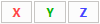
The portal robot is able to pick boxes by using a vacuum gripper. Adding a vacuum gripper is very easy in twin. You can simply add the simulation component VacuumGripper which is located in the category Gripper. You can now assign the 3d-object by clicking on near the Object3D property and then select the gripper object in the 3D View window as shown in the image below.
Add workpieces while the simulation is running
The workpieces or boxes, which will be picked by the portal robot, should be created while the simulation is running. Therefore we add a new simulation component BoxSource which is located in the category Sources. Again, we set the properties of the box source according to the following table:
| Property | Value in m |
|---|---|
| SizeX | 0.1 |
| SizeY | 0.1 |
| SizeZ | 0.02 |
| LocalOffset | [0, 0, 0.03] |
We also set the floor as the reference object for the BoxSource, so that the LocalOffset is calculated from the floor.
Tip
If you are interested, you can test the configuration now. Just start the simulation by clicking on the green play button in the 3D View window. Then you can select for example the BoxSource and toggle the Trigger input.
Tip
You can add, remove or change simulation components and 3d-objects while the simulation is running. You will love this possibility when you deal with complex machines.
Next
Now we have build the portal robot and we are ready to create a simple controller. Please move to the next chapter to proceed.