Understand the PLC program
This chapter shows you the basics of the PLC program to get a rough understanding how it works. The PLC program is made with some simplifications and could look different in a real industry project.
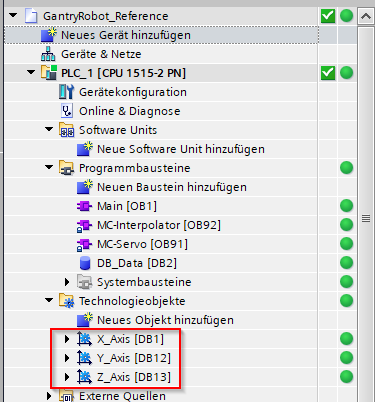
Technology objects are used for motion control
To control x-, y- and z-axis technology objects are used with enabled simulation. The PLC programmer is able to control and parametrize the axes within this software objects very easily. From the twin point of view, technology objects calculate their motions in the PLC. Therefore, this data can be used to move the physic based axes in the simulation environment by reading the actual position states periodically from the PLC.
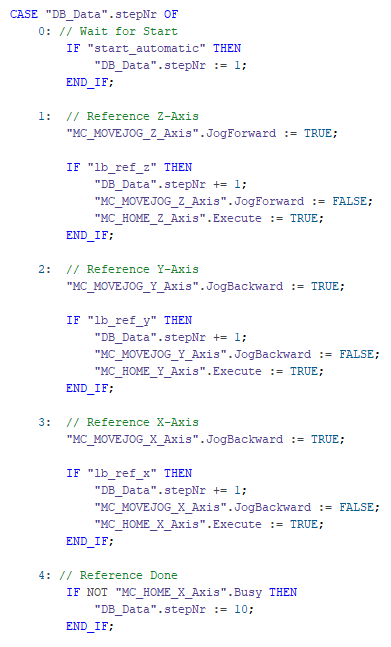
The flow control
This sample PLC project is realized by a flow control. The flow starts when the start_automatic input is triggered and stops when the stop_automatic is triggered.
The first steps are used for the reference drive. Therefore the axes are jogged successively until the responsible sensor input switches.
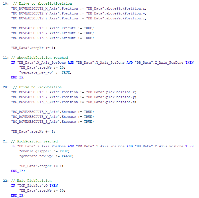
Then, the axes move with absolute positioning to the defined position to pick up the workpiece.
When the defined abovePickPosition is reached, the generate_new_wp output is set to true. Later this signal should trigger the Object3DSource to generate a new workpiece.
After reaching the defined pickPosition, the enable_gripper output is activated. This output is used to activate the vacuum on the gripper in the simulation.
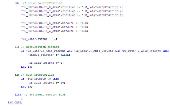
After picking up a workpiece, the axes move absolute to the defined dropPosition. After arriving, the gripper is disabled to drop-off the part.
The flow repeats until the stop_automatic is triggered.
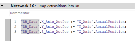
The actual positions of the axes are mapped into a DB which can be read periodically by the twin simulation. The position unit is mm.
Tip
To be able to read/write variables from PLCSim Advanced by the symbol, the check-boxes "Accessible from HMI/OPC UA/Web API" and "Visible in HMI engineering" must be checked.
Next
In the next chapter we adapt the existing gantry robot twin project and add new sensors and control buttons to the machine.