DynamicObjectDetector
This simulation component is a camera like component which can detect any dynamic objects within a defined view.

When to use
Use this simulation component if you want to detect any dynamic objects within its view frustum.
For example, this component could be used to simulate a bin-picking system.

How to use
Add this simulation component from the simulation component library. Select a 3D object which should be used as the reference system either in the 3D view or in the assembly structure window using the template select button. Then define the view frustum with help of the available properties.
Note
The simulation component only detects dynamic rigid body's if the simulation is running.
Note
The simulation component works like a real camera. If a dynamic object lies under another object, this object will not be detected.
Parameters
FieldOfView
A value in degree, indicating the total field of view.
LocalLookDirection
A vector in the 3D objects local coordinate system, indicating the look-direction of the camera. This indicates the z-axis of the camera coordinate system.
LocalOffset
A vector in the 3D objects local coordinate system, indicating the origin of the view frustum.
LocalUpVector
A vector in the 3D objects local coordinate system, indicating the up-direction of the camera. This indicates the negative x-axis of the camera coordinate system.
LookDistance
A value in m, indicating the distance of the image plane.
Object3D
The associated 3D object.
Resolution
a value indicating how many points are scanned in each image direction.
Outputs
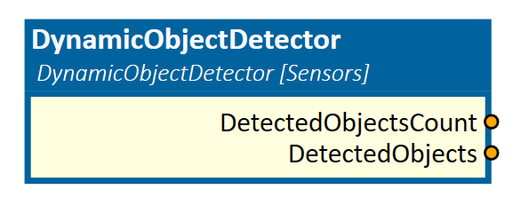
DetectedObjects
An output containing the detected 3D objects and their poses relative to the specified Object3D.
DetectedObjectsCount
An output indicating how many dynamic 3D objects are detected within the view frustum.
Example
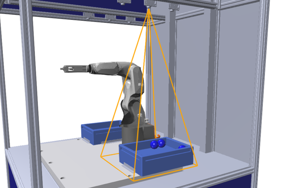
In this example, the camera side of a bin-picking system is realized. Therefore the DynamicObjectDetector simulation component is used.
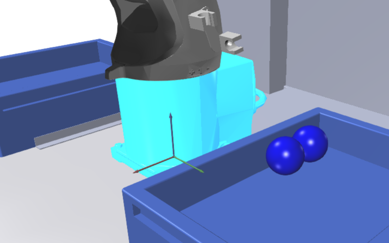
To realize a system similar to the system which is showed in the picture above, the FieldOfView must set to 27 degrees. The robot base is defined as the Object3D as shown below.

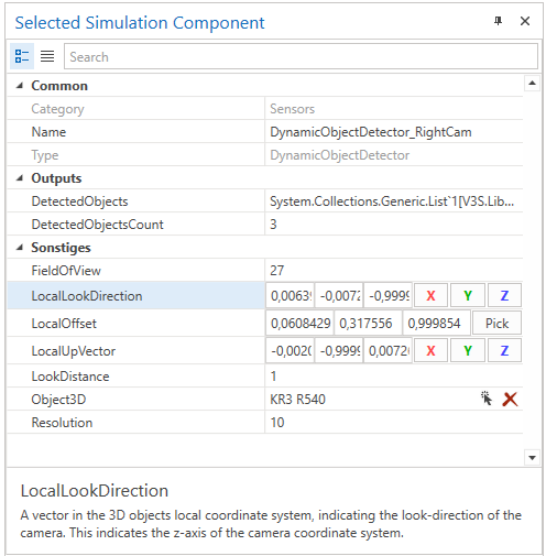
The LocalLookDirection is in the negative z-direction of the robot base coordinate system. For the LocalOffset the position of the real camera is selected.
The negative x-direction is defined as the LocalUpVector. The LookDistance is set to 1 m and the Resolution is defined as 10 as shown in the following picture.

The detected objects could now be processed by a script component to find the best object 3D to pick and moved by the robot.