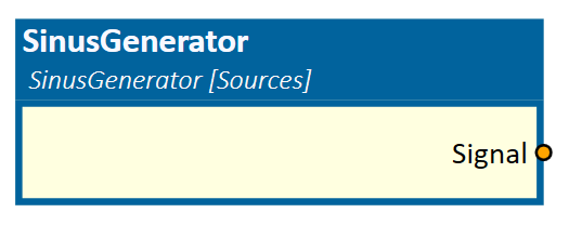
SinusGenerator
This simulation component outputs a configurable sinus signal.
When to use
Use this simulation component if you want to output a configurable sinus signal.
How to use
Add this simulation component from the simulation component library. Define the properties Amplitude, Frequency, Mean and PhaseOffset and start the simulation to generate the signal.
Note
The SinusGenerator outputs a sinus signal only if the simulation is running.
Parameters
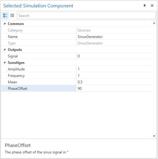
Amplitude
Indicates the amplitude of the sinus signal.
Frequency
Indicates the frequency of the sinus signal in Hz.
Mean
Indicates the constant value added to the sinus signal. Also known as bias.
PhaseOffset
Indicates the phase offset (shift) of the sinus signal in degrees.
Outputs
Signal
Outputs the waveform by the given formula:
Signal = Amplitude * sin (2 * PI * Frequency * SimulationTimeInSeconds + PhaseOffset * PI/180) + Mean
Example
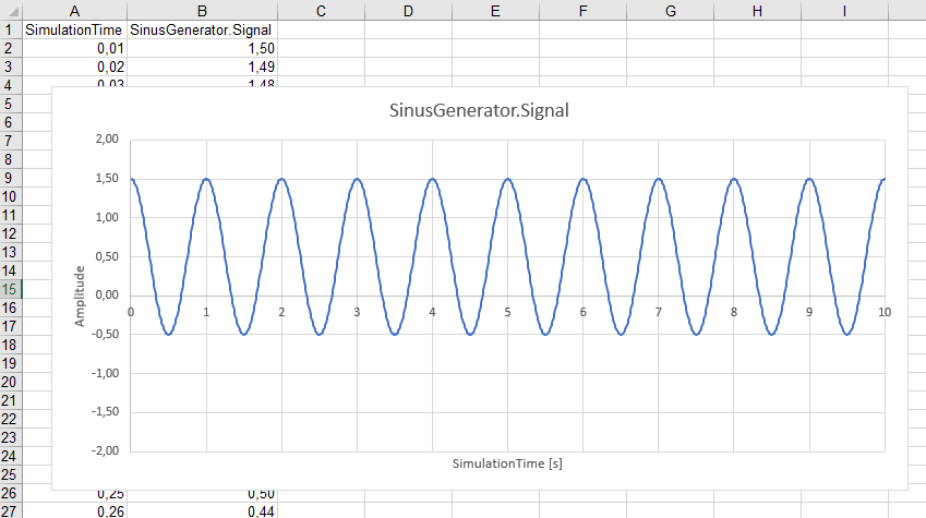
In this example, the generated output Signal is recorded by the FileLogger simulation component, which logs the input data into a csv-File.

The defined parameters of the sinus signal are shown in the picture below.
In the chart below, which is created within the *.csv-File, the periodic generated oscillation with an Amplitude of 1, a Frequency of 1 Hz, a Bias of 0.5 and a PhaseOffset of 90 degrees is shown.
Further Information
For more details visit the Video Guides section, where you can find a video guide demonstrating this topic under Add 3D-Object with random pose to the simulation.
Further Information
For more details visit the Video Guides section, where you can find a video guide demonstrating this topic under Data Logging.