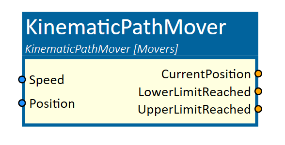
KinematicPathMover
This simulation component moves 3D objects or groups of 3D objects along a free definable path.
When to use
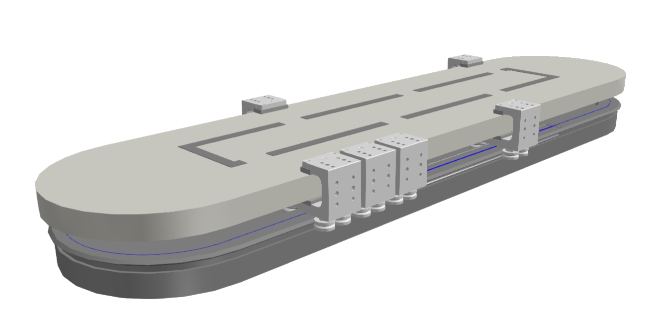
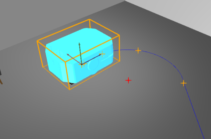
Use this simulation component if you want to move 3D objects relative to their parents along a created path. The translation is done by setting either the position or the speed of the movement. With this simulation component you can build up e.g. mover systems or AGV paths. In the picture below, the created path is used to simulate a mover system with a curved track form.
How to use
Add this simulation component from the simulation component library. At first select a 3D object or an assembly either in the 3D View window or in the Assembly Structure window which should move around the path using the select button near the property MovingObject3D.
Then define forward and up vector in global or local coordinates of the selected MovingObject3D. The forward vector indicates the forward direction, the up vector must be orthogonal.
In the next step you need to define the path by adding segments (e.g. line or arc segment) to the Path property by clicking the Add button.
Another option is to create a new path in the context menu of the AssemblyTree.
This path can later be selected using the PathObject3D. It can also be used by other path mover components.
Finally you can define the ControllingType which indicates whether the 3D object should be moved by setting the position or the speed of the movement.
Parameters
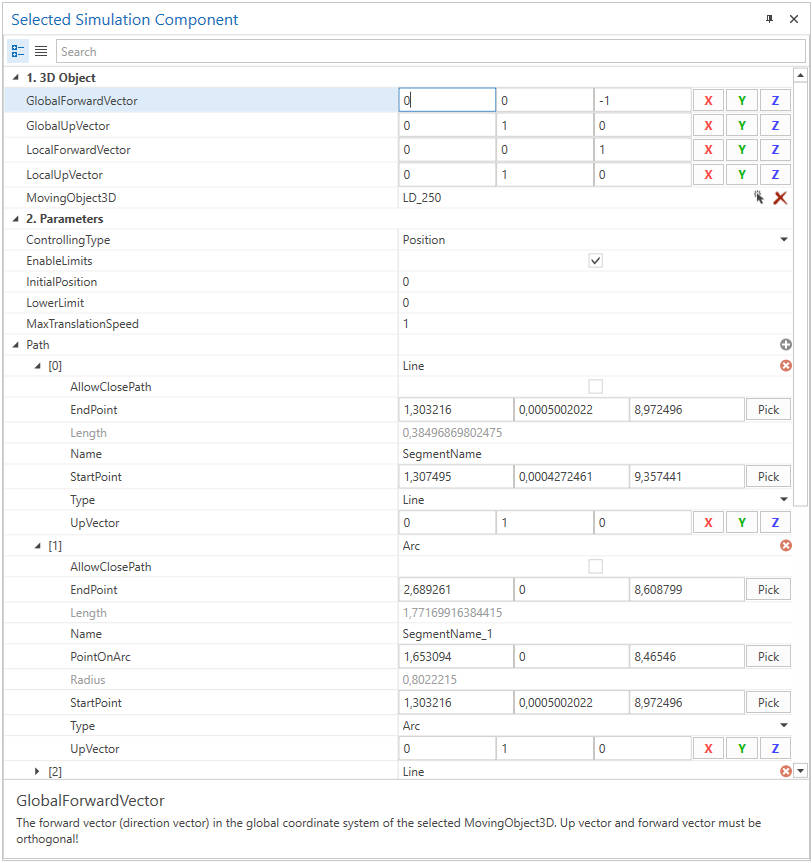
GlobalForwardVector
The forward vector (direction vector) in the global coordinate system of the selected MovingObject3D.
GlobalUpVector
The up vector in the global coordinate system of the selected MovingObject3D.
Note
The up vector and forward vector must be orthogonal.
LocalForwardVector
The forward vector (direction vector) in the local coordinate system of the selected MovingObject3D.
LocalUpVector
The up vector in the local coordinate system of the selected MovingObject3D.
MovingObject3D
The 3D object which will be moved along the path. The rigid body behavior of this 3D object and any children must be either None or Kinematic.
ControllingType
Indicates if the 3D object should be moved by setting the position or the speed of the movement.
EnableLimits
A value indicating whether upper and lower limits are enabled or not.
InitialPosition
A value in m indicating the initial position on the path of the MovingObject3D.
LowerLimit
Indicates the lower limit of the translation on the path in m.
UpperLimit
Indicates the upper limit of the translation on the path in m.
MaxTranslationSpeed
Indicates the maximum translation speed in m/s on the path. When the parameter ControllingType is set to Speed, the input Speed is multiplied by this factor.
PathObject3D
Describes the path on which the MovingObject3D moves. When this property is set, the Path-Property will be ignored.
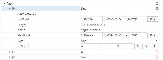
Path
Describes the path on which the MovingObject3D moves.
| Type of segment | Description |
|---|---|
| Line | Indicates a Line segment which is defined by a start- and an endpoint. |
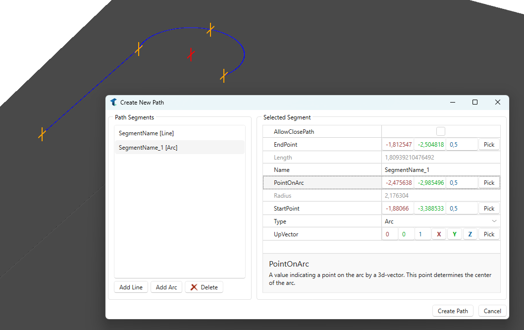
| Arc | Indicates an Arc segment which is defined by three points: A start- and endpoint and a third point PointOnArc which indicates a point on the arc. |
General segment properties
| PropertyName | Description |
|---|---|
| StartPoint | A value indicating the start position of the segment by a 3d-vector. |
| EndPoint | A value indicating the end position of the segment by a 3d-vector. |
| AllowClosePath | A value indicating if the path could get closed by this segment if it is the last segment. Therefore, the EndPoint of the current segment will be set equal to the StartPoint of the first segment. |
| UpVector | A value indicating a reference vector which helps to identify the coordinate system of the segment. Normally, the GlobalUpVector of the movement direction is used. |
Arc
| PropertyName | Description |
|---|---|
| PointOnArc | A value indicating a point on the arc by a 3d-vector. This point determines the center of the arc. |
Inputs
Position
An input in m indicating the target position of the translation.
Speed
An input indicating the speed of the movement in fractions of the parameter MaxTranslationSpeed. 1.0 means 100% of the parameter MaxTranslationSpeed.
Outputs
CurrentPosition
Outputs a value in m indicating the current position of the moving Object3D on the path.
LowerLimitReached
Outputs a value indicating whether the lower limit of the translation on the path is reached or not.
UpperLimitReached
Outputs a value indicating whether the upper limit of the translation on the path is reached or not.
Example
In this example, the position output of a ServoMotor simulation component is used to move an AGV on the created path which represents the navigation path.
Therefore, the local z-axis of the selected MovingObject3D is defined as the LocalForwardVector. The y-axis of the object 3D is the LocalUpVector.
The path consists of some segments, beginning with a Line segment followed by a Arc segment.
Start- and endpoints are indicated by the orange markers which are visible when the KinematicPathMover simulation component is selected.
For more details visit the Video Guides section, where you can find a video guide demonstrating this topic under Moving an AGV along a Path.