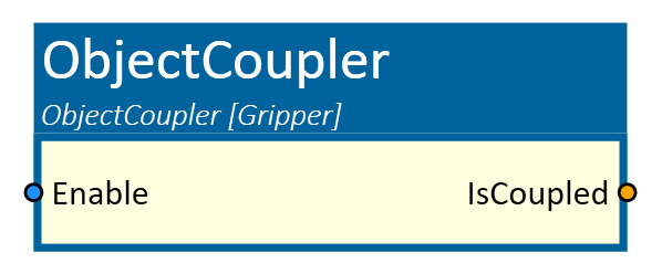
ObjectCoupler
With this simulation component, a 3D object is defined as a flange, which can then be coupled with any non-dynamic 3D object or group of 3D objects.
When to use
This simulation component is used when you want to couple a 3D object or a group of 3D objects to another 3D object with a signal. This transfers the movement of the flange 3D object to the gripper 3D object. Signals from the gripper and signals to the gripper can be transfered with this component. This simulation component can be used to simulate a gripper change for a robot.
How to use
Add this simulation component from the simulation component library. Assign a 3D object to the property Flange.
If a true signal is applied to the input Enable, the flange object couples with the nearest gripper object that is withing the search radius.
The gripper object follows the flange object until the input signal returns to false. To transfer signals from the grippers to another destination and vice versa,
define NumberSignalsFromGripper to create a specific number of inputs for the number of grippers used, or
define NumberSignalsToGripper to create a specific number of outputs for the number of grippers used.
This enables the signals of the active gripper to be looped through to the target and the signals that are to be
looped through to the gripper to be forwarded to the active gripper.
Note
The property RigidBodyBehavior of the selected flange can be of any type. The RigidBodyBehavior of the selected gripper objects must not be Dynamic.
Parameters
Flange
The base 3D object that couples with the gripper 3D objects.
Gripper
A 3D object that can be coupled with the flange.
GlobalSearchOrigin
A point in the global coordinate system that defines the center of the gripper search sphere. With help of the pick button, this point can be moved as required.
SearchRadius
The search radius determines the space (in the shape of a geometric sphere) in which a gripper must be located so that it can be coupled with the flange.
ShowSearchRadius
If activated, the area in which the ObjectCoupler searches for defined Grippers is displayed in the 3D View window.
NumberSignalsFromGripper
A number which defines the amount of inputs for every gripper and outputs for the specific number.
NumberSignalsToGripper
A number which defines the amount of outputs for every gripper and inputs for the specific number.
Inputs
Enable
A boolean input that couples the flange on a rising edge and decouples on a falling edge.
Outputs
IsCoupled
A boolean output that indicates if the flange is coupled or not.
Example
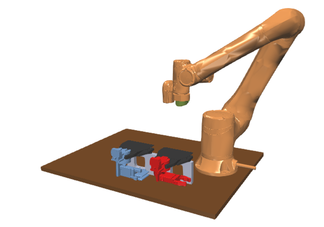
In this example, the green 3D object (Gripper-Flange) is assigned as Flange, the blue gripper (2-Finger-Gripper) as Gripper_1 and the red gripper (Claw-Gripper) as Gripper_2.
The search radius is defined as 0.5m.
This example demonstrates how a gripper change is implemented with the ObjectCoupler simulation component.
In the picture below, no gripper is coupled with the robot flange. When the robot now moves to one gripper, in this case to the red one,
and the Flange input is set to true and the gripper is within the SearchRadius, the gripper becomes coupled to the flange object.
Subsequently, as the robot moves, the gripper follows the flange's movement, as depicted in the following image.
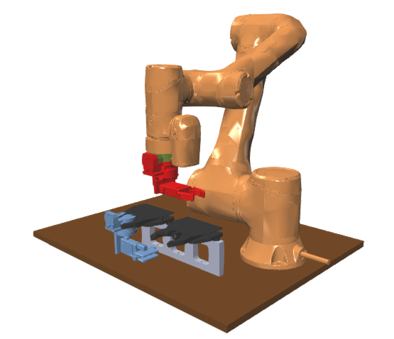
The IsCoupled output is also set to true, if the gripper change was successful.
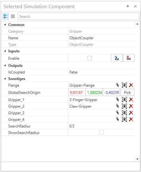
The picture below illustrates an instance of the ObjectCoupler component.
The numerical values assigned to NumberSignalsFromGripper and NumberSignalsToGripper determine the number of input and output signals. In this example, there are 2 grippers, 3 input signals from grippers, and 1 output signal to grippers.
Which results in a total of 8 inputs and 6 outputs. The 1 standard input and output and 3 input signals from each gripper to 3 outputs to an other component. Also 1 input from an other component to 1 output for each gripper.
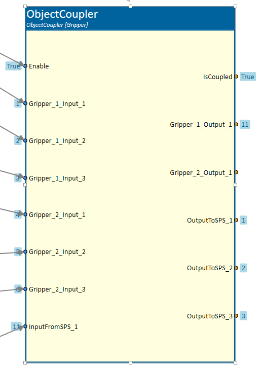
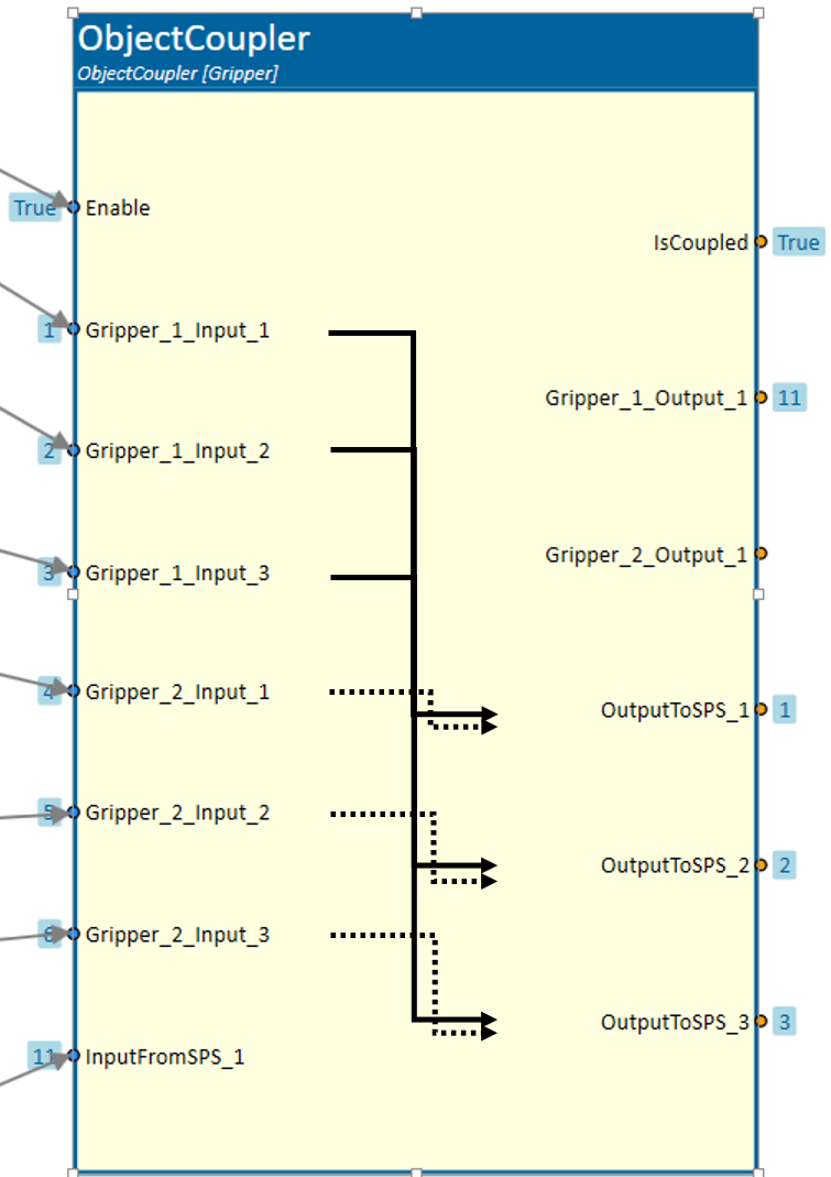
Consequently, there are 6 inputs (3 for each gripper) where the signals from the grippers are received, and 3 outputs exclusively for signals from the active gripper, labeled as "Gripper_1" in this case.
The parameter NumberSignalsToGripper determines the number of inputs (1 in this case) for signals from another component, along with 2 outputs (1 for each gripper) directing signals exclusively to the active gripper.
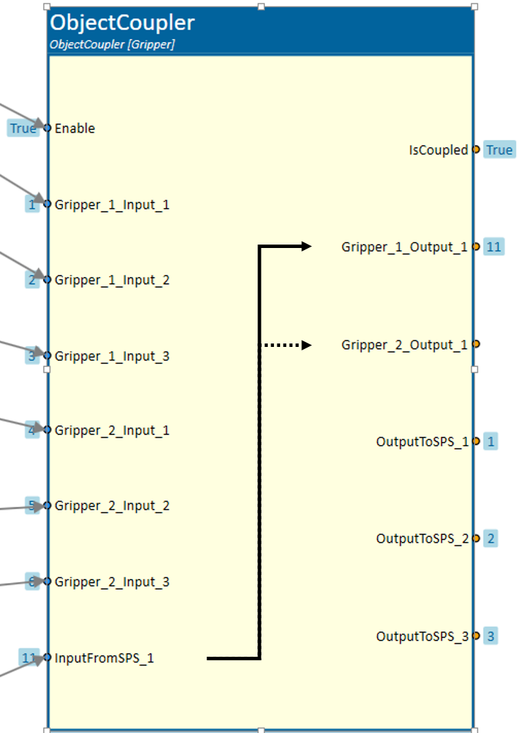
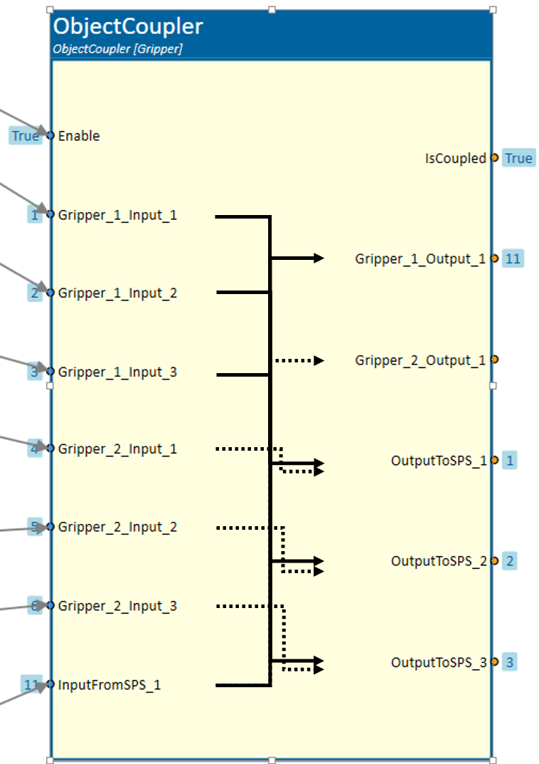
All gripper signals serve as inputs, but only the signals from the active gripper are sent to the outputs. Inputs from other components are directed solely to the outputs of the active gripper.
Note
The specific values of NumberSignalsFromGripper and NumberSignalsToGripper, in conjunction with the number of grippers, determine how many inputs and outputs the object coupler has.
Note
The gripper objects must not be part of the robot kinematics.