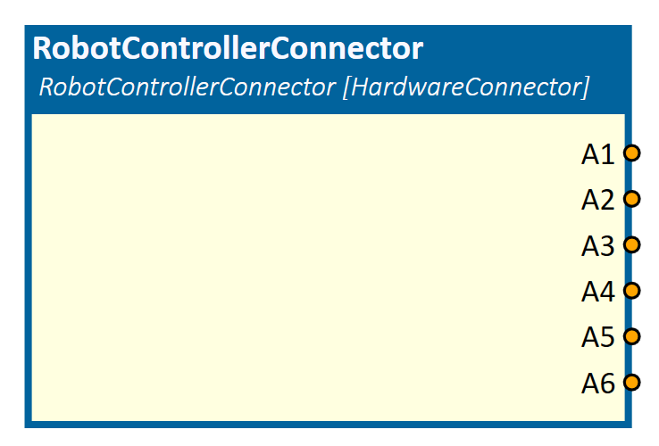
RobotControllerConnector
This simulation component connects to a Robot Controller and allows to read output-values from that controller and write input-values to that controller.
When to use
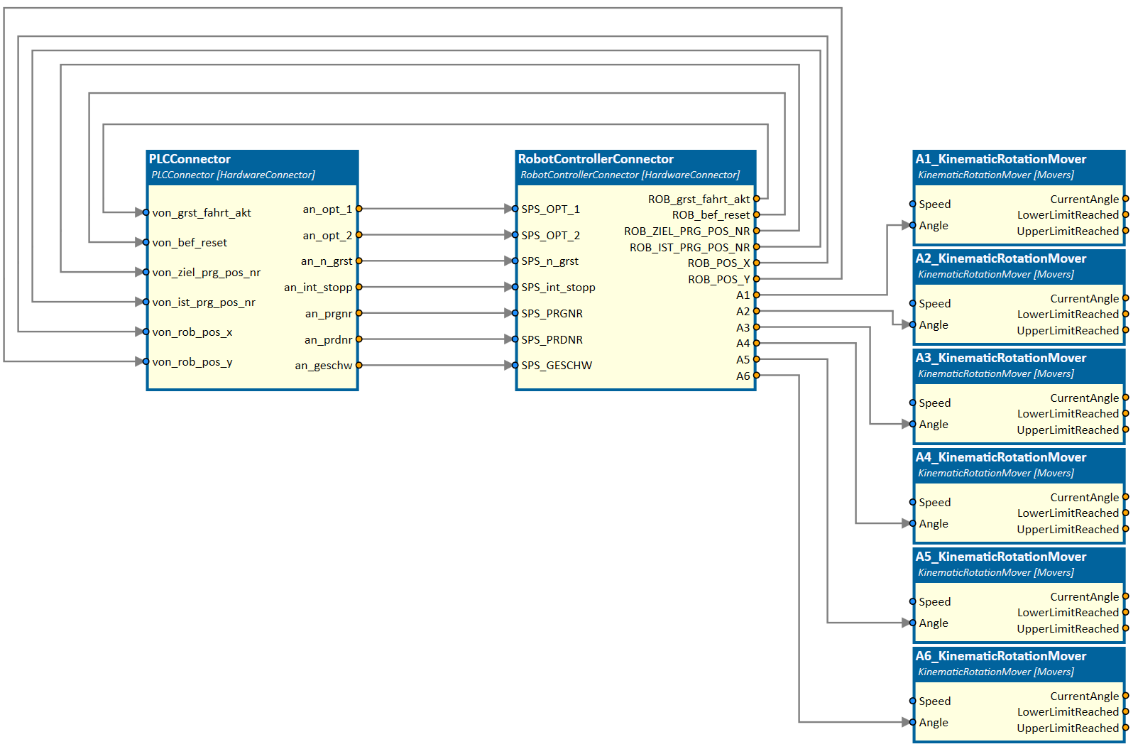
Use this simulation component if you want to send or receive datapoints from either a real or a simulated Robot Controller. For example, if you connect the PLCConnector simulation component to the RobotControllerConnector simulation component, as seen on the image below, the PLC is able to control the procedure's of the robot program inside the Robot Controller.
The angle outputs of the Robot Controller are used to rotate the six axes of a 3D robot model with the help of the KinematicRotationMover simulation component.
How to use
Add this simulation component from the simulation component library. To configure the connection to a Robot Controller please select the type of the Robot Controller protocol and adapt the settings for the selected protocol. Inputs and outputs of that simulation component are created by importing a datapoint file. The datapoint file defines, which values should be written to or read from the Robot Controller.
Tip
You can edit all properties of the Robot Controller while the simulation is running. You can change the datapoints and even the type of controller.
Parameters
Import Datapoint file
Here you can select the datapoint file from which datapoints are imported. You can see a message in the status bar at the bottom of the app when the import process has finished. For all imported datapoints a corresponding input or output is created.
InputsCount
The number of inputs, which are imported from the datapoint file.
IsConnected
A value indication whether a connection to the Robot Controller is established or not. The value is only updated, when the simulation is running.
OutputsCount
The number of outputs, which are imported from the datapoint file.
Protocol
The protocol which is used to connect to the Robot Controller. You can choose one of the following protocols:
| Protocol | Description |
|---|---|
| FanucPCDK | Connect to the ROBOGUIDE virtual Robot Controller from FANUC. |
| KRC4 | Connect to the KUKA.OfficeLite virtual Robot Controller from KUKA. |
| KRC4C3Bridge | Connect to the KUKA.OfficeLite virtual Robot Controller from KUKA. |
| UR | Connect to the virtual Robot Controller URSim from Universal Robots. |
| MotoSim | Connect to the virtual Robot Controller MotoSim from YASKAWA. |
Settings
Here you can change the protocol specific settings according to the tables below.
FanucPCDK
| Name | Description |
|---|---|
| Hostname | The host name or IP address of the target virtual robot. Click ROBOGUIDE menu Robot/Default Browser to open the robot home page. |
| Port | The port of the target virtual robot in ROBOGUIDE. This refers to the 'Robot IF Server' port number. |
| ConnectionTimeoutInMS | The communication timeout in milliseconds. Valid range is between 100 ms and 10,000 ms. |
| ArrayIndexOffset | The array offset for configuring datapoints (e.g., 1 means EasArray[1] = GO[1]). |
Please ask for a default datapoint file to add datapoints to your simulation component.
KRC4
| Name | Description |
|---|---|
| IPAddress | The hostname or IP-address of the remote machine where KUKAVARPROXY is running. |
Examples for symbolic access, specified in the datapoint file:
| Type | DataFile |
|---|---|
| System variable (read-only) | $IN_HOME |
| Variable | ROB_POS_X |
Note
Only variables created by the user can be written. System variables like "$ON_PATH, $IN_HOME" can only be read. Variables, created by the user, need to have an assigned datype like INT, BOOL or REAL on the robot controller.
UR
| Name | Description |
|---|---|
| IPAddress | The hostname or IP-address of the remote machine where the virtual UR controller is running. |
Examples for symbolic access, specified in the datapoint file:
Tip
The UR driver uses the Real-Time Data Exchange (RTDE) protocol to read/write variables from/to the URSim. Check the developer's guide (https://www.universal-robots.com/articles/ur/interface-communication/real-time-data-exchange-rtde-guide/) for the names and types of the controller IO's for creating the datapoint file.
MotoSim
| Name | Description |
|---|---|
| IPAddress | The IP-address of the remote machine where the virtual robot controller in MotoSim is running. |
| Port | The port which is defined in the MotoSim twin-Plugin. |
Tip
For each robot controller or robot in MotoSim, create a new RobotControllerConnector instance, choose the corresponding robot or controller in the MotoSim twin-Plugin, assign a unique port number, and establish a connection to this port.
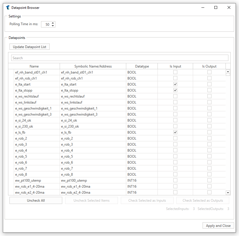
BrowseDatapoints
This property is visible if the corresponding protocol provides datapoint browsing e.g. Moto Sim or UR.
If the button next to the property is clicked, twin starts a separate window to browse visible datapoints of the connected controller. The following picture shows how this looks like if a controller is connected. If no controller is connected, no datapoints will appear.
Inputs
After a datapoint file is imported successfully, all defined inputs are listed here. If the simulation is running, the value is sent to the Robot Controller as soon as it changes.
Outputs
After a datapoint file is imported successfully, all defined outputs are listed here. If the simulation is running, the value is read periodically from the Robot Controller. The update interval can be defined in the datapoint file.
Example
In this example, a connection to the virtual Robot Controller KUKA.OfficeLite is established.
First, we need to add the RobotControllerConnector simulation component from the simulation component library. Then we select KRC4 as the target Robot Controller to connect with and in the settings we define the hostname of the remote machine where the KUKAVARPROXY is running.
To get access to the inputs and outputs of the Robot Controller we have to import a datapoint file where these inputs and outputs are defined. After importing these datapoints, a corresponding input or output is created for this simulation component. These inputs and outputs can now be freely connected to other simulation components.
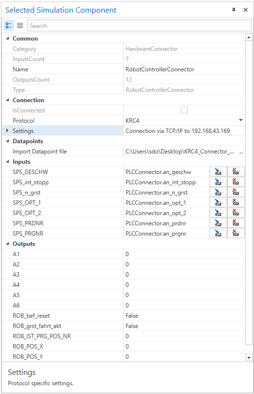
The properties of the configured RobotControllerConnector simulation component look like this:
Further Information
For more details visit the Video Guides section, where you can find a video guide demonstrating this topic under Connect to MotoSim.