PLCConnector
This simulation component connects to a PLC via a configurable protocol and allows to read output-values from that PLC and write input-values to that PLC.
When to use
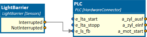
Use this simulation component if you want to send or receive datapoints from either a real or a simulated PLC. For example, if you connect the simulation component LightBarrier to the simulation component PLC, as seen on the image below, the signal of that light-barrier is sent to the connected PLC input and you can use the value within the PLC program.
How to use
Add this simulation component from the simulation component library. To configure the connection to the PLC please select the protocol and adapt the settings for the selected protocol. Inputs and outputs of that simulation component are created by importing a datapoint file. The datapoint file defines, which values should be written to or read from the PLC.
Tip
You can edit all properties of the PLC while the simulation is running. You can change the datapoints and even the connection protocol.
Parameters
Import Datapoint file
Here you can select the datapoint file from which datapoints are imported. You can see a message in the status bar at the bottom of the app when the import process has finished. For all imported datapoints a corresponding input or output is created.
InputsCount
The number of inputs, which are imported from the datapoint file.
IsConnected
A value indication whether a connection to the PLC is established or not. The value is only updated, when the simulation is running.
OutputsCount
The number of outputs, which are imported from the datapoint file.
Protocol
The protocol which is used to connect to the PLC. You can choose one of the following protocols:
| Protocol | Description |
|---|---|
| OPC-UA | Connect to an OPC-UA server. |
| Siemens S7 | Connect to a Siemens PLC with the native S7 protocol. To use this protocol for S7-1200 or S7-1500 CPUs you must disable block compression within TIA Portal. |
| Siemens Simit Unit | Connect to the Siemens Simit Unit. |
| Siemens PLCSIM Advanced | Connect to the virtual controller Siemens PLCSIM Advanced. |
| Beckhoff ADS | Connect to any device which supports the Beckhoff ADS protocol. |
| Datapoint Manager | Connect to the datapoint manager from Eberle Automatische Systeme. |
Settings
Here you can change the protocol specific settings according to the tables below.
OPC-UA
| Name | Description |
|---|---|
| Authentication | The mode used for authentication on the server. You can select between anonymous mode or authentication by username and password. |
| Hostname | The hostname or IP-address of the OPC-UA server. |
| Namespace | The namespace used to locate the symbolic variables which are defined in the datapoint file. |
| Password | The password, if authentication is set to Username And Password |
| Username | The username, if authentication is set to Username And Password |
| ReadAlwaysFromDevice | Enable continuously polling of datapoint values. If enabled, the performance is may be reduced. Only enable if necessary or OPC-UA server does not support monitoring. |
Examples for symbolic access, specified in the datapoint file:
| Type | DataFile |
|---|---|
| IDB | "idb_krc4_anst"."in"."von_bereit" |
| Struct | "db_platzdaten"."platz_info"[1]."pal_vorhanden" |
| Others | ns=1;s=ConveyorSlideSensorsMechanic:slideEntrySensor |
Tip
Check the OPC-UA server with help of an OPC-UA client (f.e. the dataFEED OPC-UA client from Softing) to find out, how the symbolics are specified in the server.
Siemens S7
| Name | Description |
|---|---|
| Hostname | The hostname or IP-address of the PLC. |
| Rack | The rack number of the PLC. |
| Slot | The slot number of the PLC. |
Examples for addressed access, specified in the datapoint file:
| Type | DataFile |
|---|---|
| 1 BIT (BOOL) output variable | A 0.0 |
| 1 BIT (BOOL) input variable | E 0.0 |
| 16 BIT (f.e.: UINT16, INT16) output variable | AW 1 |
| 32 BIT (f.e.: UINT32, INT32) input variable | ED 3 |
Siemens Simit Unit
| Name | Description |
|---|---|
| ProjectFilename | The directory of the project which will be downloaded to the Siemens Simit Unit. This project can be created with the Siemens Simit Unit app. |
| SimitUnitAppPath | The directory where the Siemens Simit Unit app is installed. |
| TimeoutInMS | A timeout in ms for calls to the Siemens Simit Unit. |
Examples for addressed access can be found in the section Siemens S7.
Siemens PLCSIM Advanced
| Name | Description |
|---|---|
| InstanceName | The name of the PLC instance which is running on the Siemens PLCSIM Advanced software. |
| Port | If remote host has been specified, a remote connection can be established to another Runtime Manager via the specified port. Default port is 50000. |
| RemoteHost | If no remote host has been specified, the communication corresponds to the local communication via Softbus, otherwise it corresponds to the communication via TCP/IP. |
| TagType | Indicates, if datapoints are accessed either by their address or by their symbolic names. |
Examples for symbolic access, specified in the datapoint file:
| Type | DataFile |
|---|---|
| Single variable | a_bel_trig_1 |
| Struct or IDB | ent_antr_zsw.ZSW1.NoFlwErr |
Examples for addressed access can be found in the section Siemens S7.
Note
As of twin 25.8, only Siemens S7-PLCSIM Advanced 6 and higher is supported.
Earlier versions of twin support Siemens S7-PLCSIM Advanced 4.1 and higher.
Beckhoff ADS
| Name | Description |
|---|---|
| AmsNetId | The NetId of the ADS device. |
| Port | The port used to connect to the ADS device. |
Examples for symbolic access can be found in the section Siemens PLCSIM Advanced.
BrowseDatapoints
This property is visible if the corresponding protocol provides datapoint browsing e.g. Siemens PLCSIM Advanced or Beckhoff ADS.
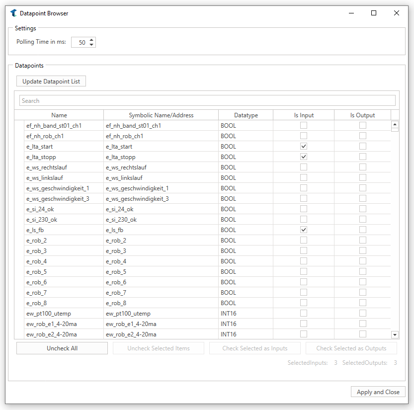
If the button next to the property is clicked, twin starts a separate window to browse visible datapoints of the connected controller. The following picture shows how this looks like if a controller is connected. If no controller is connected, no datapoints will appear.
Properties
| Properties | Description |
|---|---|
| PollingTime | The „Polling Time“ property indicates the polling time cycle of the declared outputs. In this case, the outputs are read every 50 ms from the controller by twin. |
Columns
| Columns | Description |
|---|---|
| Name | The „Name“ column indicates the declared name of the variable in the controller. |
| Symbolic Name/Address | The „Symbolic Name/Address“ column indicates how the variable is identified in the controller. This could be a symbolic name (like in this case) or an address. |
| Datatype | The „Datatype“ column indicates the declared datatype of the variable in the controller. |
| IsInput | If this checkbox is enabled, the corresponding variable will be used as input by twin and will be created in the component as input as well. If the value of this variable changes, twin writes this value to the connected controller. |
| IsOutput | If this checkbox is checked, the corresponding variable will be used as output by twin and will be created in the component as output as well. The value will be read within the defined polling cycle. |
Buttons
| Buttons | Description |
|---|---|
| Update Datapoint List | If this button is triggered, all Inputs and Outputs are read and listed from the connected controller again. |
| Uncheck All | This button unchecks all checked Inputs and Outputs. |
| Uncheck Selected Items | This button unchecks all Inputs and Outputs of the selected items. |
| Check Selected as Inputs | This button checks the Input property of all selected items. |
| Check Selected as Outputs | This button checks the Output property of all selected items. |
| Apply and Close | This button loads all selected Inputs and Outputs and provides them as Inputs and Outputs in the simulation component. Inputs and Outputs that are not checked anymore will be deleted from the simulation component. |
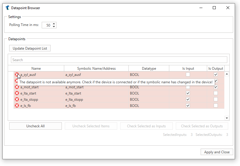
If Inputs and Outputs that are already loaded in the simulation component are not available anymore in the controller or the controller is not connected, property errors are shown. This could look like the following picture.
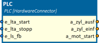
Inputs
After a datapoint file is imported successfully, all defined inputs are listed here. If the simulation is running, the value is sent to the PLC as soon as it changes.
Outputs
After a datapoint file is imported successfully, all defined outputs are listed here. If the simulation is running, the value is read periodically from the PLC. The update interval can be defined in the datapoint file.
Example
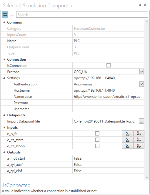
In this example, a connection to a PLC via OPC-UA is established. First, we need to add the simulation component PLC from the simulation component library. Then we select OPC-UA as the protocol and in the settings we define the hostname of the PLC we want to connect to. In this example we connect to a Siemens PLC so we do not have to modify the namespace. We also do not use any kind of authentication.
To get access to the inputs and outputs of the PLC we have to import a datapoint file where these inputs and outputs are defined. After importing these datapoints, a corresponding input or output is created for this simulation component. These inputs and outputs can now be freely connected to other simulation components.
The properties of the configured simulation component PLC look like this:
Further Information
For more details visit the Video Guides section, where you can find a video guide demonstrating this topic under Connect to PLC Sim Advanced and create IOs using the datapoint browser.