Sequence
With this simulation component, you can create a sequence by simply dragging and dropping blocks and use it to control your machine.
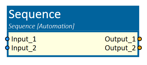
When to use
Use this simulation component when you want to control the behavior of a machine using task sequences. This is particularly useful for prototyping automation processes, designing logical flows, or building state machines without programming.
The sequence component is especially suitable for concept studies or simulation scenarios where task-based logic (e.g. waiting for input, setting outputs, moving a robot) needs to be modelled visually and executed during simulation.
How to use
Add this simulation component from the simulation component library. Then define the inputs and outputs the sequence should have in InputDefinitions and OutputDefinitions.
In the properties of the component, click the edit button next to Sequence to open the editor. The editor always contains the main block of the sequence, which has three sections:
| Section | Description |
|---|---|
Variables |
Create your variables here, each with a name and an initial value. |
First Run |
These blocks are executed once after the simulation has been started. Use this section to bring the machine into its start state, e.g. by setting outputs. |
Loop |
These blocks are executed after First Run and are repeated endlessly as long as the simulation is running. |
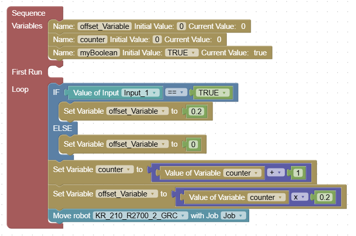
Now you are ready to visually model the sequence by dragging blocks from the toolbox on the left of the editor into these sections. The toolbox groups the blocks by category; all blocks are described under Blocks below. Use them, for example to read inputs, modify variables, set outputs or move robots.
Press Apply Sequence to transfer the sequence to the simulation. Changes in the editor have no effect until you press Apply Sequence.
While the simulation is running, the block that is currently being executed is highlighted in the editor, and the variable declarations show the current value of each variable.
When the simulation is reset, all variables are set back to their initial values and the sequence starts again with First Run.
Tip
The blocks can be modified while the simulation is running. As soon as Apply Sequence is pressed, the current arrangement of the blocks is applied. It is like programming a PLC online.
Tip
Click Info in the top right corner of the editor to see the available keyboard shortcuts, e.g. for undo and redo, copying blocks, selecting several blocks or zooming.
Parameters
InputDefinitions
A list of the inputs the sequence has. Add an entry for every input you need and define its name and data type (Bool, Double, Integer or String). You can link these inputs to other simulation components and you can then use the values of the inputs within the sequence by waiting for a specific value or simply reading out the current value.
OutputDefinitions
A list of the outputs the sequence has. Add an entry for every output you need and define its name and data type (Bool, Double, Integer or String). You can link these outputs to other simulation components and you can then change the values of the outputs within the sequence.
Sequence
The sequence itself, modelled visually by blocks with different tasks. Use the edit button to open the editor. Changes are applied after you have pressed Apply Sequence in the editor.
Inputs
An input is created for every entry in InputDefinitions, with the name and data type defined there.
Outputs
An output is created for every entry in OutputDefinitions, with the name and data type defined there.
Blocks
I/O
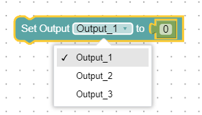
Set Output 'output' to 'value'
This block allows you to select a configured output from a dropdown menu and assign a value to it.
Wait until Input 'input' is 'value'
This block allows you to select a configured input from a dropdown menu. The block completes once the input reaches the specified value.

Value of Input 'input'
This block provides the current value of an input. The value can be used in conditions, calculations or assignments.
Robot
Move robot 'robotController' with Job 'job'
This block lets you select a robot controller and one of its jobs from dropdown menus. It sends the movement command to the robot and waits until the movement is completed.

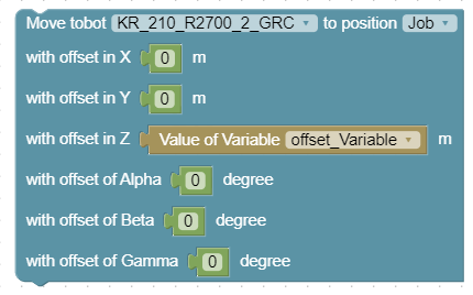
Move robot 'robotController' with Job 'job' with offset
This block lets you select a robot controller and one of its jobs from dropdown menus. You can also specify offsets in X, Y and Z (in m) and in Alpha, Beta and Gamma (in degrees), relative to the robot's base coordinate system. The block sends the movement command with the offsets to the robot and waits until the movement is completed.
Statements
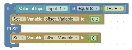
If-Else-Statement
The If-Else block compares two values with the selected operator.
If the comparison is true, the blocks in the IF branch are executed; otherwise, the blocks in the ELSE branch are executed.
| Operator | The comparison is true if ... |
|---|---|
== |
both values are equal. |
!= |
the values are not equal. |
< |
the first value is smaller than the second value. |
> |
the first value is larger than the second value. |
% |
the first value is divisible by the second value without remainder. |
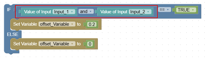
Logic condition 'value' 'operator' 'value'
This block combines or compares two values and provides the result, True or False, as a value.
Use it to build more complex conditions, e.g. to check two inputs at once within an If-Else block.
Besides the comparison operators of the If-Else block, the following operators are available:
| Operator | The result is True if ... |
|---|---|
and |
both values are True. |
or |
at least one of the values is True. |
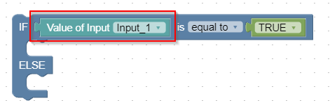
In the following example, the logic condition (marked with a red frame) is plugged into the first value of an If-Else block and compared with TRUE. The IF branch is only executed if Input_1 and Input_2 are both True.
Time
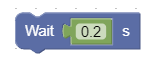
Wait 'value' s
The Wait block allows you to specify a time in seconds. Once the time has elapsed, the block is completed.
Utility
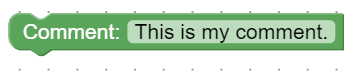
Comment block
The Comment block can be used to add any kind of notes or comments.
Constants
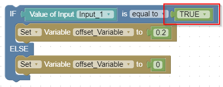
Boolean Constant
This block allows you to specify a Boolean constant, either True or False.
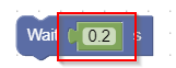
Numeric Constant
This block allows you to specify a numeric constant, including values with decimals (floating point).
Variables
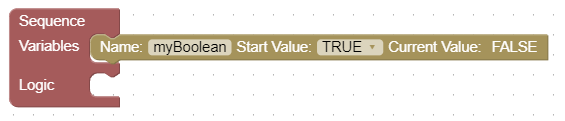
Declaration of a Boolean variable
A Boolean variable can be created with an optional initial value. This variable can then be used in various blocks to set values or for comparisons. While the simulation is running, the block shows the current value of the variable.
Declaration of a numeric variable
A numeric variable can be created with an optional initial value. This variable can then be used in various blocks to set values or for comparisons. While the simulation is running, the block shows the current value of the variable.
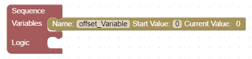
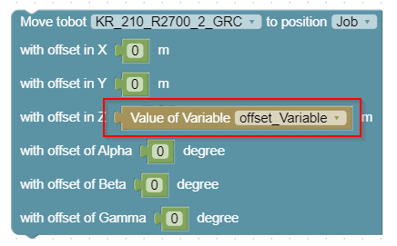
Value of Variable 'variableName'
This block allows you to use the current value of the variable, selected via the dropdown, in different blocks for setting values, calculations or comparisons.
Set Variable 'variableName' to 'value'
This block assigns a new value to the variable selected via the dropdown.
To increase, decrease or otherwise change the current value, combine the block with a calculation block,
e.g. set the variable counter to counter + 1 by plugging a calculation block with Value of Variable counter and the constant 1 into it (see Math below).

Math
Calculation 'value' 'operator' 'value'
This block calculates a result from two values and provides it as a value, e.g. for the Set Variable block or as an offset of a robot movement. Calculation blocks can be nested to build longer formulas.
| Operator | Result |
|---|---|
+ |
Sum of both values. |
- |
The first value minus the second value. |
x |
Product of both values. |
÷ |
The first value divided by the second value. |
^ |
The first value raised to the power of the second value. |
In the following example, Set Variable offset_Variable to counter x 0.2 calculates the offset of the next layer from a counter. The calculation block is marked with a red frame.

Example
In this example, a simple sequence using blocks is shown, in which a box is conveyed forward on a conveyor belt and then picked up and stacked by a robot.
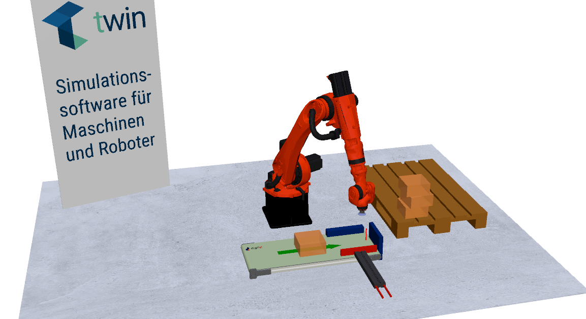
As soon as the light barrier is interrupted and a delay time has elapsed, the box is aligned by a cylinder.
After alignment, the box is picked up and stacked by a robot.
In First Run, the robot moves to its pre-position once. The stacking pattern is generated dynamically: the variable offsetZ is used as the Z offset of the placing movements and is increased by 0.2 m at the end of each cycle.
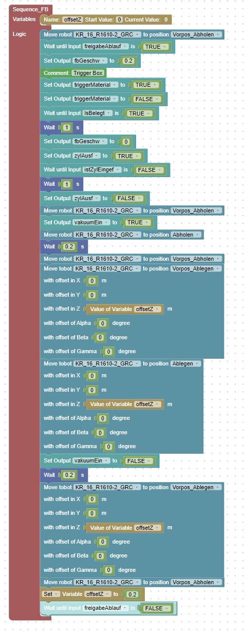
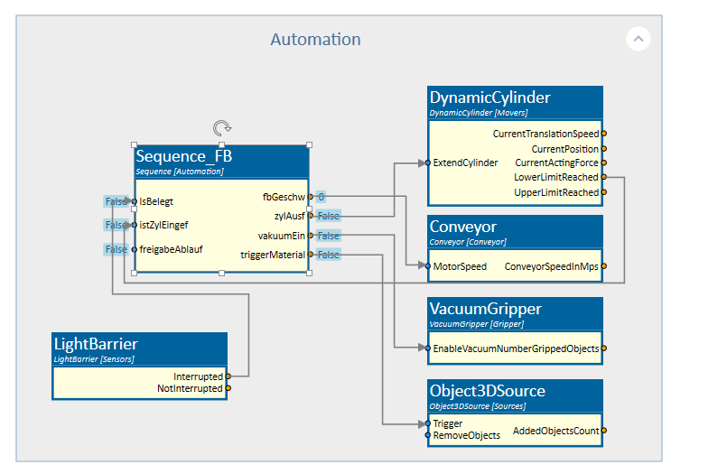
The following image shows the component diagram. It illustrates how the sequence communicates with the actuators and sensors.
One output directly controls the conveyor belt. Another output is responsible for extending the cylinder. A separate output triggers the source of the box, and another activates the vacuum at the gripper. Additionally, there is feedback from the cylinder sensor indicating whether the cylinder is retracted, as well as from the sensor detecting whether the box has reached the front.
The sequence is started manually.
Further Information
For more details, visit the Video Guides section, where you can find a video guide demonstrating this topic under Graphical programming of sequences.